Define Layered Sections
Layered Sections in Advance Design allow the definition and management of multi‑layer planar cross‑sections, such as CLT panels, used by layered shell planar elements for FEM analysis and design.
Contents
Overview
Layered Sections are used to model planar elements composed of multiple material layers with specific thicknesses and orientations. They are primarily associated with layered shell planar elements and are required for workflows such as CLT modelling and advanced orthotropic behaviour.

Access to the Layered Sections Manager from the Manage tab
Layered Sections can be created, modified, imported, and managed using the Layered Sections Manager, which is available only in the Descriptive Model.
How to access the command
You can access the Layered Sections Manager using any of the following methods:
-
From the Menu: Select Edit > Layered Sections.
-
From the Ribbon: Navigate to the Manage tab, then click on the Materials and Sections panel. From there choose Layered Sections.
-
From the Properties window: For a planar element of type layered shell, place the cursor in the Layered surface section code cell and click on the corresponding icon
 .
.
Note
Layered Sections can only be defined and modified in Descriptive Model.
After launching the command using one of the above methods, the Layered Sections Manager dialog will open for you to define, customize, and manage the Layered Surface Sections.

Layered Surface Sections used to create and manage layered sections
- Add/Modify: Create a new layered section or modify an existing one.
- Purge: Delete the unused layered section(s).
- Delete: Remove selected layered section(s).
- Library section: Layered sections loaded from a database, which cannot be edited. Import them into the In-Used layered sections to make them available for customization and use in your project.
- Export: Save the In-Use Layered Sections into a .xml file for future use.
- Properties: Display the geometric and mechanical properties of layers of the selected layered shell.
- Help: Display the Help page.
- Close: Save the changes made in the Layered Sections manager and close the dialog box.
Add or modify a layered section
- Open the Layered Sections Manager
Launch the Layered Sections Manager using one of the access methods described above. - Access Add/Modify Options
In the Layered Surface Sections dialog box, click Add/Modify. The dialog expands to display configuration options.

Add or modify layered sections
- Select or Create a Layered Section
Choose an existing section from the list to modify, or create a new layered section.
Create a new layered section
If you want to create a new layered section, follow these steps:
- Optional: Use Quick Generator for Fast Setup

Layered Section Quick Generator
The Quick Generator tool helps create layers for typical CLT panels. In the generator dialog:
- Specify Material, Number of layers, and Layer thickness.
- Click Generate to automatically create layers.
All layers use the same material and thickness.
Layer angles alternate between 0° and 90° (e.g., Layer 1 = 0°, Layer 2 = 90°, etc.).
Important
Using the Quick Generator overwrites any previously defined layers. This tool provides a basic CLT section setup. Further customization can be done in the main window.
- Assign a Section Name
Enter a name for the new section.
- Choose Section Type
- CLT: Only timber materials are available, and orientation angle can be set only to 0° or 90°.
- General: All material types and orientation angles are available.
- Define Layer Properties
Using the table, define for each layer:
- Layer name
- Material
- Thickness
- Angle
- Manage Layers
Use the available buttons to:
- Add Layer
- Delete Layer
- Move Up
- Move Down
- View Stiffness Matrix
Click Stiffness Matrix to display the computed matrix for the selected section.
Available options:
- Ignore E90
- In CLT design, code-based checks typically disregard the contribution of weak layers (those oriented at 90°), assuming their stiffness is negligible.
- When Ignore E90 is enabled, the Young’s modulus perpendicular to the grain direction (E2 or Ey) is set to zero in both FEM analysis and design calculations. This ensures consistency between FEM results and design checks.
- If Ignore E90 is disabled, weak layers carry part of the load, reducing calculated stresses compared to the case where their contribution is ignored.
- Applicable only to orthotropic materials in CLT sections.
- Out-of-Plane Shear
- Stiffness Summation of Layer: Using this method, shear stiffness terms S44 and S55, can be adjusted using stiffness modifiers property of planar element.
- Equivalent Energy Method.
- Save Changes
Click Save to store the new section or apply modifications to an existing one.
Manage layered sections
Purging layered sections from the model
- Launch the Layered Surface Sections command.
- Click Purge. A confirmation message appears.
- Confirm the operation by clicking Yes.

Deleting unused layered sections
from the model
Layered sections that are not used in the model are automatically purged and a confirmation message is displayed.
Deleting a layered section
- Launch the Layered Surface Sections command.
- Select the cross section to delete from the current list.
- Click Delete. A confirmation message appears.
- Click Yes to apply.
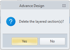
Deleting a layered section
Warning
Layered sections that are used in the current project, as well as the default layered section, cannot be deleted.

Warning when attempting
to delete a used layered section
Importing predefined layered sections from Library
- Open Layered Surface Sections manager.
- Click Library to expand the dialog box with Import options.

Library of layered sections
A custom database of layered section can be imported in the model for use.
- Import: Import selected layered sections from the Library to the In-Use Layered Sections list.
- Import All: Import all the layered sections from the Library to the In-Use Layered Sections list.
Exporting in-use layered sections
- Open Layered Surface Sections manager.
- Press Export.
- All in use layered shells will be saved in an xml file for later use.
Viewing the layered sections properties
- Open Layered Surface Sections manager.
- Select a layered section from the current list.
- Click Properties to display the geometric and mechanical attributes of the selected cross section.

Geometrical and mechanical properties of a layered section
FAQ (Frequently Asked Questions)
Where can layered sections be edited?
A: Only in the Descriptive Model.
Can layered sections be reused in other projects?
A: Yes. They can be exported to and imported from XML libraries.
Can a layered section be deleted if it is used in the model?
A: No. Used and default layered sections cannot be deleted.
Glossary
- Layered Section
- A planar cross‑section composed of multiple material layers with defined thickness and orientation.
- Layered Shell
- A planar element type that uses layered sections to model composite behaviour.
- Quick Generator
- A tool used to automatically generate basic layered sections, typically for CLT panels.