Crane Workflow
The process of analyzing crane moving loads in Advance Design is similar to the Traffic loads workflow.
The crane workflow consists in the following steps:
-
Defining the runway - adding a runway graphically by the user
-
Defining the crane load system - adding a crane object by the user
-
Defining the load case family – adding a load case by the user
-
Generating moving load cases – automatic process triggered by the user
After completing the above steps, the loads are prepared and after generating the load combinations and performing the structural analysis, the next step is to postprocess the results.
Defining the runway
The first step is to define a Runway object – the route along which loads are moved. It could be defined as a single line (for monorail cranes) or as a pair of parallel lines (for bridge cranes).
Select the appropriate command for creating a runway:
-
Ribbon > Objects tab > Moving Loads panel > Crane Runway dropdown list > Crane Runway (monorail or bridge)
-
Main Menu > Generate menu > Crane Runway (monorail or bridge)

Generating a crane runway (mono-rail or bridge)
Draw the runway lines on your model (see Defining the crane runway). The runway is stored in the Project Browser under Structure.

Crane runway display
Click on the runway to display its properties window and adjust settings (see Crane runway properties).

Crane Runway properties
Crane
The following step is to define a Crane object that stores info about the geometry of the crane and loads acting on wheels. Such loads are added either manually (then the crane object contains one set of loads) or automatically (then the crane object contains several sets of loads, to be used later as moving loads). Automatic load generation is performed by using either European or US/CAN standards provisions.
Select the appropriate command for creating a crane:
-
Ribbon> Objects tab > Moving Loads panel > Crane
-
Main Menu> Generate menu > Crane
-
Right click on the Crane runway in the Project Browser > Add crane

Adding a crane
Note:
If there is more than one runway in your project, first you need to select the one to which you want to assign a crane. Otherwise, no selection is required.
After creating a crane, select it to display its Properties window and adjust settings to define loads generated by the crane (see Crane properties).

Crane properties
Creating a crane load case family
After creating and setting the properties of the crane runway and of the crane itself, you can create a crane load family.
-
Right click on Loading in the Project Browser and select Create a case family or Create several case families.
-
In the dialog box select Crane loads and click OK.

Creating a crane loads case family
The load case family is stored in the Project Browser under Loading.

Crane loads display
The next step is to assign runways and cranes to the loads case family. For this, a special dialog window is opened from the property list of the Crane loads family. To open it, in the Crane moving parameters section click the  button from the Runway property.

Accessing the Crane system definition dialog box
The Crane system definition dialog box appears (see Crane system definition dialog box). Click Auto-detect to assign the runway and crane to the load case. You can also manually change settings (including the operating Range and the length and number of steps). Click OK to confirm.

Crane system definition
To define load cases and corresponding loads, in the Project Browser right click on Crane loads and choose Automatic generation. As a result, a list of crane load cases is created. Depending on the crane parameters (the input method for loads), one or more independent sets (groups) of moving loads are obtained. Additionally, auxiliary load combinations (only between moving loads) and force envelopes are generated.

Automatic generation of crane loads
Envelopes are generated separately for minimum and maximum reactions and forces on linear elements and include only moving loads from cranes. For a single crane, the envelopes are generated for loads from a single crane. If there are multiple cranes, the envelopes are generated from all physically possible combinations of crane positions. The envelopes of the crane loads can be used for generating load combinations with other load cases in the model (permanent, variable, wind, etc.). The use of the combination envelope significantly reduces the number of required load combinations.
Post-processing
After running the calculation, you can view the calculated crane load cases from the Ribbon > Results tab > FEM Results panel.
You can view the results in the same way as for other static load cases, by selecting cases with successive force positions (steps).

Results
Influence line
Another method for displaying results for moving loads is displaying the changes in a value of a selected quantity at a selected point, because of the movement of a load over the structure: the display of the influence lines for the selected quantity. It is available only when there are results for Traffic or Crane moving loads.
To access the Influence line dialog box first you need to select one node of the calculated model.
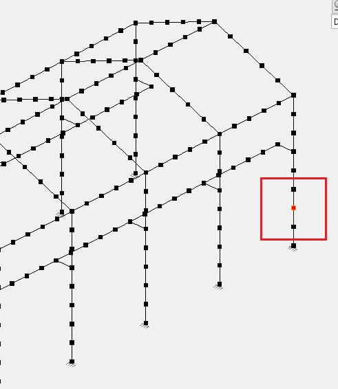
Selected node
Then access the Influence line command:
-
Ribbon > Results tab > Post Processing panel > Result Curves dropdown list > Influence line
The following dialog box appears:

Influence line dialog box
From the dropdown lists select the number of the crane and the number of the load group for which you want to display the graph. Also, select the required results (displacement) from the adjacent panel. Click Apply. In the Preview section a graph is being created.

Influence line graphic
Double click in the Preview panel area to open the Curves – Non smoothed results window. Here you can access advanced information and apply complex settings to the graph.
