Command Line
The Command Line, positioned at the bottom of the drawing area by default, stands as an important component within Advance Design, facilitating numerous aspects of the design process.

Command line in the Advance Design environment
Key Features of the Command Line
-
Provides information about the status of your current action;
-
Suggests different options to end an operation successfully;
-
Helps you draw or modify the model's elements;
-
Displays various warnings and error messages;
-
Displays parameters of the selected elements (structure elements or analyses);
-
Provides access to the program commands.
The Command Line's visibility and position, whether floating, docked, (auto)hidden, or resized can be customized within the application environment using the interface display functions.
How to display the command line
Follow one of the methods presented below to display the command line:
-
In the Drawing Area: Right-click the edge and select Command Line.
-
Through the Ribbon: Go to the Manage tab, select the Components panel, and choose Command Line.
Command line content: A Detailed Guide
The command line contains three tabs:
1. Information
Displays a list of performed actions. The bottom command line field can also help you draw/modify objects by directly typing parameters in it:

Information tab
You can easily copy or delete the command line contents using the context menu commands from the Information tab:

Copy/delete content
2. Errors
Displays errors whenever they are detected by the application (e.g.: when launching a verification of the descriptive model). Also, this tab's context menu allows you to quickly copy / delete errors, as well as to select all / highlighted errors:

Errors tab
3. Edit
Intermediates the dialog between the user and the application.
How to access commands using the command line
Using the keyboard, it is possible to access the program commands:
- In the command line field, type (part of) the name of the corresponding command:

Accessing commands using the Command line
As you begin typing the name of a command, a list of available commands containing the typed word(s) is displayed. The corresponding command can be selected by using the up and down arrows of the keyboard and pressing <Enter>. Press again <Enter> to validate the command.
- To access previously used commands, press the left arrow button of the keyboard. It is possible to scroll through the list of the recently used commands using the left and right arrows.
- The previously used commands that require entering parameters (e.g. coordinates), are displayed with full syntax. All parameters can be defined:
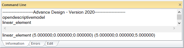
Defining parameters
How to use the command line for modeling elements
You can input or modify the model components by typing the desired parameters in the dialog area of the command line.
-
Access a drawing or a transformation tool from menus or toolbars. Note that the command line switches automatically to the Edit tab and displays a message containing the operation that must be performed next.

Using the Command line for modeling elements
-
Type the drawing or the modification parameters (separated with a space or a coma) in the dialog area of the command line and press <Enter>.

Using the Command line for modeling elements
The action is performed in the drawing area.
Note: The coordinates entered on the command line follow the order of the current plane coordinates (e.g., X Z for plan view, X Y Z for 3D view). In 3D, to input X Y Z coordinates on the command line, first, hide the workplane.
How to edit the command line content
Right-click in the command line to access commands that allow you to edit its contents:
-
Copy: copies to clipboard all contents, or only the selected part.
-
Clear: deletes all contents.
How to display the properties of the selected elements in the command line
- Select any object/group of objects from the graphic area.
- From the menu select Edit > Properties (or use the <Alt+D> shortcut).
The properties of the selected elements are displayed on the command line.

Displaying properties of a selected element in the Command line